NEC Article 700: A Practical Guide to Emergency Systems
Go deeper into our Article 700 slide series: follow emergency power from the source to the lighting, understand maintenance and testing, and learn why every part of the system matters.
Start with the whole system
The generator starts. The transfer switch operates. Somewhere down the corridor, an emergency light stays dark. Has the emergency system done its job? That question captures the central lesson of our Article 700 slide series: dependable emergency power requires every link to work, all the way from the alternate source to the equipment people rely on.
This guide brings together slides 2–50 of our 50-part series. Instead of treating each code reference as a separate fact to memorize, we will follow the system through design, installation, testing, maintenance, and later changes. The aim is to help apprentices, electricians, and facility teams ask better questions when reviewing an emergency-power installation.
Our references use the 2023 NEC, the same edition as the slides. An emergency system under Article 700 is a defined application; a building having a generator does not make every connected load an Article 700 load. Establish the required system classification with the design team and authority having jurisdiction (AHJ) before applying these rules. The locally adopted edition, amendments, equipment instructions, and project requirements govern actual work. This is an educational walkthrough, not a complete design or switching procedure. [1]
Picture the path on a one-line diagram: source, transfer equipment, distribution, branch circuit, controls, and final load. Beside that path, add the people and records needed to keep it available. A failure in either column can leave an apparently finished installation unable to perform when needed.
Commission it, test it, and keep the evidence
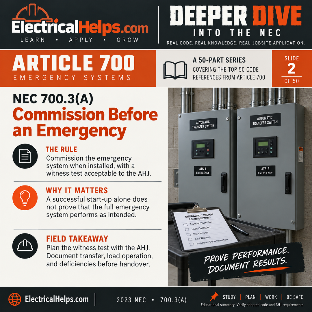
Slides 2–6 begin with 700.3(A) through (E). Commissioning, periodic testing, maintenance, written records, and testing under maximum anticipated load conditions belong together. In the 2023 edition, 700.3(A) calls for the AHJ to conduct or witness commissioning when the system is installed and periodically afterward. Leviton highlights this change from the earlier testing language. [2]
A useful commissioning plan explains what the system is expected to do and how the team will demonstrate it. For a lighting application, that means looking beyond a running engine or an illuminated indicator. The review needs to connect source availability, transfer operation, control response, and the intended emergency lighting. The approved test plan should define the conditions, observations, and acceptance criteria before the test begins.
The owner must arrange periodic testing on a schedule acceptable to the AHJ. Maintenance under 700.3(C) also involves manufacturer instructions and applicable industry standards. Avoid inventing one universal interval for every component. Batteries, transfer equipment, controls, and the source can have different maintenance needs, even though they serve one system.
Imagine a test report that simply says “passed.” Now compare it with one that identifies the equipment, test conditions, measured results, unresolved defects, corrective work, and retest date. The second record gives the next technician something useful to act on. A means for testing under maximum anticipated load conditions also matters: an unloaded run cannot demonstrate how the installation responds when its emergency loads actually operate.
Plan for the day the emergency source needs maintenance
An alternate source will eventually need service. Slides 7–13 ask what supports the emergency system while that source is unavailable. Under 700.3(F), a system relying on a single alternate source generally needs permanent switching means for a temporary source during maintenance or repair, unless a stated exception applies. [3]
The connection arrangement needs to be planned before the outage. Our slides call attention to connecting without changing permanent system wiring, identifying phase rotation and bonding requirements, and preventing unintended source interconnection. In the 2023 rule, the switching means and interlocks are listed, with mechanical or combined mechanical and electrical interlocking. An improvised connection or a bypassed interlock defeats the purpose of planning the arrangement.
Other details make the plan usable: a remote indication that the permanent emergency source is disconnected; an outdoor temporary-generator connection point; and a cable route that does not pass through exterior doors, windows, or similar openings. The permanent connection label identifies voltage, maximum amperage, the short-circuit current rating of the supplied load-side equipment, and ungrounded conductors.
Think through the arrival of a rental generator during bad weather. Where will it sit? Can the intended cables reach the approved connection point while keeping access routes usable? Who verifies compatibility, bonding, phase rotation, and the operating sequence? These are planning questions for qualified personnel. A matching plug shape or a promise to “make it work” is not a substitute for a reviewed arrangement. Check each exception against the actual site conditions rather than treating an exception as a general waiver.
Size for starting, changing loads, and the right priorities
Slides 14–17 shift from availability to capacity. Section 700.4(A) requires adequate capacity determined by a permitted calculation or approved method, including expected rapid changes in load and transient power and energy demands. A steady operating total tells only part of the story. The source must also respond when equipment starts or when several loads arrive close together.
Consider two systems with the same steady load. One picks up small loads gradually; the other receives a large step change. Their operating totals may look similar on a schedule, yet their demands on the source can be very different. The designer needs the real load characteristics and intended sequence, and the test plan should reflect that sequence.
Section 700.4(B) addresses priorities when a source also serves other loads. Where load management is needed, emergency loads take priority over legally required standby loads, which take priority over optional standby loads. A convenience load must not consume capacity needed by the emergency system. Keep the load schedule current, including additions made after the original installation.
Slide 17 also flags parallel operation with the normal source under 700.4(C)(1) and Article 705. Running in parallel is a distinct operating condition requiring an appropriate interconnection design. It is not a mode to enable simply because a controller offers the setting. Document the approved modes so future operators understand what the installation was designed to do.
Treat transfer equipment as a critical part of the path
Slides 18–24 cover equipment that decides which source reaches the emergency loads. Section 700.5(A) requires automatic transfer equipment identified for emergency use and approved by the AHJ, with protection against inadvertent source interconnection. Section 700.5(C) addresses electrically operated, mechanically held automatic transfer switches, with specific permissions elsewhere in the article. Selecting a switch by amperage alone misses its intended function.
The maintenance question applies here too. A working source cannot supply a load through a transfer path that has been removed from service. Under 700.5(D), emergency loads supplied by a single feeder generally require redundant transfer equipment or a bypass-isolation transfer switch, subject to the section’s exceptions. If that maintenance path is manual, a qualified person must actively supervise it while the primary automatic equipment is disabled. [3]
The written-emergency-plan exception highlighted in slide 23 has real content: mitigation actions, responsibilities for qualified persons, and the recognized site hazards for the maintenance period. The plan must be implemented and available to the AHJ. A generic document in a folder does not explain how this particular building will be protected during this particular outage.
Section 700.2 also prohibits reconditioned transfer switches in emergency systems. Verify equipment provenance during procurement. Distinguish that purchasing restriction from the maintenance obligations for installed equipment; the series is not suggesting that required maintenance should stop. The practical goal is a transfer arrangement that can be identified, operated, serviced, and documented throughout its life.
Make the emergency distribution path recognizable and resilient
Slides 25–30 follow power into the distribution system. Section 700.8 requires listed surge protection in or on emergency-system switchgear, switchboards, and panelboards. Include the surge protective devices in the equipment review and maintenance walkdown; installing a device once is not the same as noticing a later status indication that needs attention. [4]
Section 700.10(A) addresses identification. Our series highlights permanent identification of emergency boxes and enclosures, markings at intervals of 25 feet or less on exposed runs where boxes or enclosures are absent, and distinctive identification of emergency-supplied receptacles. The point is recognition along the route, including places a future crew may encounter during an alteration.
A clearly marked panel does not identify every unmarked run leaving it. Follow the path on the drawing and compare it with accessible field conditions. Confirm that the circuit directory, equipment labels, and actual supplied loads agree. A receptacle’s color is a clue to verify, not proof that its source or circuit assignment is correct.
Physical location matters as much as identification. Section 700.10(C) addresses hazards such as fire, flooding, icing, and vandalism; 700.10(D) adds fire-protection requirements for specified applications. A route exposed to the same event that threatens the normal supply deserves careful review. Establish the applicable occupancy and protection requirements early, while routing and equipment-location decisions can still be coordinated.
Low-voltage emergency lighting still needs a deliberate wiring plan
Slides 31–35 focus on Class 2 emergency lighting. “Low voltage” does not mean the circuit has no life-safety function. Section 700.11 addresses these systems, including identification, wiring arrangements, and protection. The line-voltage supply and Class 2 emergency lighting control devices remain subject to the applicable 700.10 requirements. [5]
Trace both sides of the power supply. Our slides highlight identification near connectors and along exposed runs, separation from bundled nonemergency Class 2 circuits, and the prescribed mechanical protection. Review the exact wiring method and any claimed exception. Do not assume that a cable may follow an ordinary network bundle merely because its connectors look familiar.
Section 700.27 adds another product-selection question for devices combining control and Class 2 emergency power on one circuit: is the device listed for emergency lighting control? A general-purpose network component is not interchangeable just because it communicates successfully in normal operation.
For example, a ceiling renovation may leave the power supply untouched while moving the cables and controls serving emergency lights. That work still deserves an emergency-system review. Check the revised route, connectors, protection, and intended emergency behavior before closing the ceiling. Small physical changes can affect a function that was previously demonstrated during commissioning.
Separate three questions: how fast, how much, and how long?
Slides 36–42 bring timing and stored energy into focus. Section 700.12 requires emergency power within the time needed for the application, with an upper limit of 10 seconds. That is a system-performance requirement. Starting an engine within the limit does not by itself demonstrate that usable power reached the intended load within the required time.
Capacity asks how much load the source can support. Duration asks how long it can support that load. Under the 2023 numbering used in our series, 700.12(C) generally calls for at least two hours of supply, with specific emergency-illumination and battery-equipped-luminaire provisions that differ. The required mission may also demand more than the minimum. Never apply one runtime number to every source and application. [6]
A simple energy example helps separate the concepts. A constant 5 kW load operating for two hours uses 10 kWh at the load. That arithmetic is not a battery-sizing specification: usable capacity, conversion losses, temperature, aging, required margins, and the equipment’s permitted application still need evaluation. A product’s advertised energy capacity alone does not establish emergency-system suitability.
Section 700.12(E) permits specified stored-energy sources when the applicable requirements are met. Slide 41 emphasizes fire protection, suppression, ventilation, and separation considerations. Section 700.12(H) addresses listed battery-equipped emergency luminaires. Whether the source is centralized or within a luminaire, review the complete arrangement, its supply connection, and its response to the relevant loss of normal power.
Emergency lighting needs the right control response
Slides 43–46 address the final part of the path. Section 700.19 prohibits emergency lighting and power circuits from being part of a multiwire branch circuit. That is a circuit-arrangement question to resolve during design and rough-in, before treating conductor selection as a routine repeat of a normal-lighting detail.
Now picture an occupied space with its lights dimmed. If emergency power becomes available but the lighting retains an inappropriate dimming command, source transfer alone has not demonstrated the required illumination. Under 700.24, directly controlled emergency luminaires have an emergency listing requirement, with a specific provision for arrangements where a listed emergency lighting control device disconnects the control input and establishes the required illumination. Verify the actual product combination and response. [7]
Section 700.25 covers listed branch-circuit emergency-lighting transfer switches for lighting branch circuits rated 20 amperes or less, subject to its conditions. Section 700.26 covers automatic load control relays (ALCRs). An ALCR can override normal lighting controls to energize emergency lighting; it cannot serve as transfer equipment. These devices solve different problems even when both appear in a lighting-control discussion.
Ask two separate questions on the drawings: where is the power source selected, and where is normal lighting control overridden? Then make sure the approved test plan demonstrates both functions. Product substitutions need the same review. A replacement that dims normally is not necessarily a replacement that behaves correctly during an emergency.
Keep a fault from interrupting more of the system
Slides 47–50 finish with selective coordination under 700.32. The objective is to isolate an overcurrent at the appropriate protective device while preserving service to unaffected loads. The required review includes the emergency-system devices and their supply-side and load-side relationships; it is not enough to compare the ampere numbers printed on two breakers.
Imagine a fault on one emergency lighting branch. If an upstream device also opens unnecessarily, other emergency circuits can lose power with it. A larger upstream ampere rating alone does not prove that this will be avoided. The exact protective devices, their operating characteristics, and their settings need to match the documented coordination selections.
Section 700.32(A) assigns selection to a licensed professional engineer or other qualified persons engaged primarily in electrical-system design, installation, or maintenance. The selection must be documented and available to authorized personnel. Sections 700.32(B) and (C) require reevaluation after protective-device replacements and system modifications, additions, or deletions. [3]
That makes coordination an ongoing responsibility. Replacing a breaker with one carrying the same ampere rating, removing a load, or expanding a panel can trigger review. Keep the one-line diagram, equipment records, settings, and coordination documentation aligned. Do not change a protective setting simply to make a nuisance trip disappear without evaluating the complete protection scheme.
Use the series for a better project walkthrough
The most useful outcome of this series is a habit: trace the full emergency function and ask what evidence supports it. You can practice that habit with drawings and records before entering an equipment room. It helps connect the individual code references to the people, equipment, and conditions they address.
For an existing facility, start with the current one-line diagram, emergency load schedule, equipment information, test records, and maintenance plan. Mark gaps as questions for the responsible designer or qualified maintenance team. A missing record does not prove an installation has failed, but it identifies something that needs resolution rather than assumption.
- Define the mission: which loads are emergency loads, what must they do, and which adopted requirements apply?
- Follow the path: source, transfer equipment, distribution, controls, and final loads. Compare the drawings with the installed arrangement.
- Review availability: required response time, load capacity, operating duration, and the plan for source or transfer-equipment maintenance.
- Review evidence: commissioning, periodic tests, corrective work, coordination selections, and changes made since the last review.
Sources & further reading
[1] NFPA 70 — National Electrical Code ↗
Edition basis: 2023 NEC, Article 700. This article synthesizes ElectricalHelps slides 2–50; the slide numbers above let readers follow the original series. Consult the adopted code for complete requirements and exceptions.
[2] Leviton — Commissioning of Emergency Systems ↗
2023 NEC 700.3(A): commissioning terminology and the role of the AHJ.
[3] Eaton — 2023 NEC Code Changes ↗
Cross-check for 700.3(F), 700.5(D), and 700.32. See printed pages 43–44 and 15 for temporary power, transfer-equipment maintenance, and coordination.
[4] Leviton — NEC Requirements for Surge Protection ↗
See the 700.8 discussion for emergency-system distribution equipment.
[5] Leviton — Class 2 Powered Emergency Lighting Systems ↗
2023 NEC 700.11: the dedicated section for Class 2 emergency lighting wiring.
[6] Schneider Electric / IEEE IAS Atlanta — 2023 NEC Changes ↗
Slides 91–92 discuss 700.12(C) supply duration and 700.12(E) stored-energy sources.
[7] ETC — Directly Controlled Emergency Luminaires ↗
Updated April 2023; explains 700.24 and the control-input-disconnection provision.