Understanding NEC 310.15(C)(1): Conductor Ampacity Adjustment Factors
Follow our nine-conductor example from 55A to 38.5A, understand the terminal-temperature check, and learn when a 40A breaker is permitted.
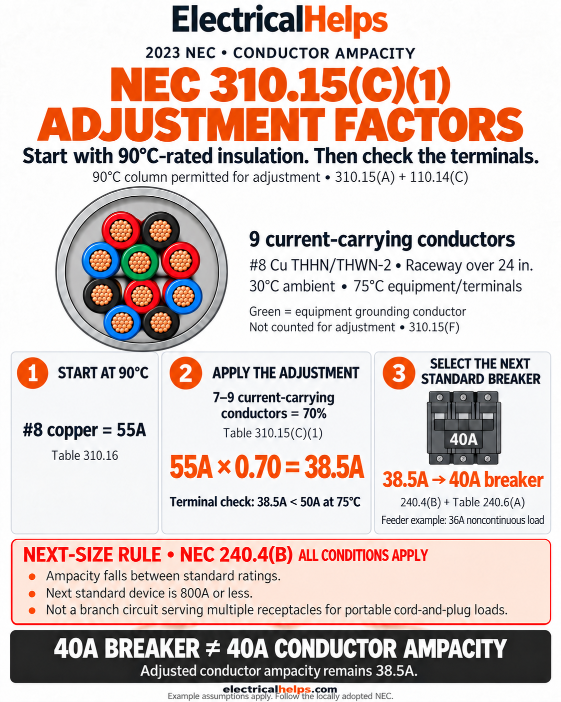
Why conductors need an adjustment factor
How can a conductor with an ampacity of 38.5 amperes be protected by a 40-amp breaker? Our graphic connects several different NEC rules. Understanding what each rule does makes the calculation much easier to follow.
Current creates heat. Packing more current-carrying conductors together makes that heat harder to dissipate. Section 310.15(C)(1) addresses this by reducing the allowable current for the installation. The percentage describes how much ampacity remains; a 70% factor means keeping 70%, not subtracting 70%.
This guide follows the 2023 NEC. Use the locally adopted edition, amendments, and equipment instructions for actual installations. The example explains conductor sizing; it is not a complete installation design.
Read Table 310.15(C)(1)
The rule generally applies when a raceway or cable contains more than three current-carrying conductors. It also addresses conductors or cables installed together without maintained spacing outside raceways for more than 24 continuous inches. Section 310.15(C)(1)(b) exempts conductors in raceways no longer than 24 inches; other specific provisions must be checked for the wiring method. [1]
Choose the row using the conductor count, then multiply the applicable ampacity by its factor. The first row below is a baseline for comparison, not an additional row in the NEC adjustment table. [2]
| Current-carrying conductors | Ampacity retained | Multiplier |
|---|---|---|
| 1–3 | 100% — no count adjustment | 1.00 |
| 4–6 | 80% | 0.80 |
| 7–9 | 70% | 0.70 |
| 10–20 | 50% | 0.50 |
| 21–30 | 45% | 0.45 |
| 31–40 | 40% | 0.40 |
| 41 or more | 35% | 0.35 |
Count conductors correctly: 310.15(E) and (F)
Our raceway contains three separate three-phase, three-wire feeders: three phase conductors per feeder × three feeders = nine current-carrying conductors. There are no neutrals. The green equipment grounding conductor shown in the graphic is excluded under 310.15(F). It still occupies physical space for raceway-fill calculations.
Neutral counting depends on the circuit. Under 310.15(E)(1), a neutral carrying only the imbalance of the other conductors of the same circuit need not count. Under (E)(2), the neutral counts in a three-wire circuit using two phases and the neutral of a four-wire, three-phase wye system. Under (E)(3), it counts on a four-wire, three-phase wye circuit when the major portion of the load is nonlinear. [1]
The table note also includes spare conductors, subject to the stated exclusions. Do not omit a wire merely because today’s load is small. Count each current-carrying conductor in a parallel set separately. [1, 2]
Start with Table 310.16 and the insulation rating
Our assumptions are 8 AWG copper THHN/THWN-2, a raceway longer than 24 inches, 30°C ambient, and equipment and terminations identified for 75°C. Each feeder supplies a calculated 36A noncontinuous load.
Table 310.16 gives 8 AWG copper 55A in the 90°C column and 50A in the 75°C column. These are starting values under the table’s conditions, not an automatic breaker selection. [2]
Section 310.15(A), together with 110.14(C), permits correction and adjustment using the conductor’s applicable insulation-temperature rating, while respecting termination limits. Thus, the example starts with 55A. Verify the actual marking and environment: THHN’s 90°C dry-location rating is not permission to use THHN alone in a wet location; the THWN-2 rating supports 90°C wet or dry use. [3]
Apply 70%, then check the terminals
Nine current-carrying conductors fall in the 7–9 row. Multiply the 90°C value by 0.70: 55A × 0.70 = 38.5A. This calculation applies to each affected conductor, not to a combined ampacity for all three feeders.
Now apply 110.14(C). Our identified 75°C terminations impose a 50A limit for this conductor size. Compare the adjusted value with that limit: 38.5A is below 50A, so 38.5A governs. Starting the calculation at 90°C never changes a 75°C equipment rating.
Section 310.15(B)(1) and Table 310.15(B)(1)(1) handle ambient-temperature correction separately. At our 30°C ambient, the factor is 1.00. When another correction applies, multiply the applicable factors together before checking the terminal limit. [2]
Why a 40A breaker? 240.4(B) and 240.6(A)
Section 240.6(A) identifies standard overcurrent-device ratings, including 35A and 40A. Since 38.5A falls between them, 240.4(B) can permit the next higher standard rating. It is a conditional allowance, not ordinary rounding. All three conditions must apply: [4]
- The conductor ampacity does not match a standard fuse or circuit-breaker rating.
- The next higher standard rating selected does not exceed 800A.
- The conductors are not part of a branch circuit supplying more than one receptacle for portable cord-and-plug-connected loads.
The breaker rating does not increase conductor ampacity
Our feeder example meets those three conditions: 38.5A is nonstandard, the next rating is 40A, and these conductors supply feeders. The calculated 36A noncontinuous load is below 38.5A. Each feeder can therefore use a 40A breaker under the stated assumptions. A 40A load would exceed the adjusted ampacity in this example.
Article 215 adds the feeder load checks. Section 215.2(A) requires both the conductor sizing check before correction/adjustment and the check after those factors are applied. Section 215.3 addresses feeder overcurrent protection. Continuous loads generally introduce 125% sizing requirements, subject to applicable exceptions; do not carry this 36A noncontinuous example over unchanged to a continuous load. [5]
Other rules remain applicable. Section 240.4(D), for example, limits protection for small conductors; the next-size allowance does not erase those limits. [4]
What changes when the count reaches ten?
Ten current-carrying conductors move into the 50% row. With the same 8 AWG copper and ambient conditions, 55A × 0.50 = 27.5A. That is insufficient for the example’s 36A load. Reevaluate conductor size or circuit routing and repeat every check; changing the breaker alone cannot restore lost ampacity.
Remember the sequence: establish the load and conditions, count conductors, select the starting ampacity, apply correction and adjustment, check terminals, and then select permitted protection. Conduit fill, grounding, and equipment-specific requirements still need their own checks.
Sources & further reading
[1] Mike Holt: Conductors, based on the 2023 NEC ↗
Conductor counting, adjustment scope, and neutral/grounding rules.
[2] HELU: 2023 NEC allowable ampacity tables (PDF) ↗
Table 310.16, Table 310.15(C)(1), and ambient-temperature factors. Match the correct table and conductor material.
[3] Southwire: THHN/THWN-2 copper conductor specifications ↗
Manufacturer temperature and location ratings; verify the product actually installed.
[4] Mike Holt: Overcurrent Protection, based on the 2023 NEC ↗
Next higher standard rating conditions and small-conductor limitations.
[5] Mike Holt: Feeders, based on the 2023 NEC ↗
Feeder conductor sizing, continuous loads, and overcurrent protection.
NFPA 70: National Electrical Code ↗
Publisher’s access to the NEC. Consult the complete adopted edition and applicable local amendments.